|
Motor de Búsqueda de Datasheet de Componentes Electrónicos |
|
|
Motor de Búsqueda de Datasheet de Componentes Electrónicos |
|
LTC1735CF Datasheet(PDF) 14 Page - Linear Technology |
|
|
|||||||||||||||||||||||||||||
LTC1735CF Datasheet(HTML) 14 Page - Linear Technology |
|
|
14 / 32 page 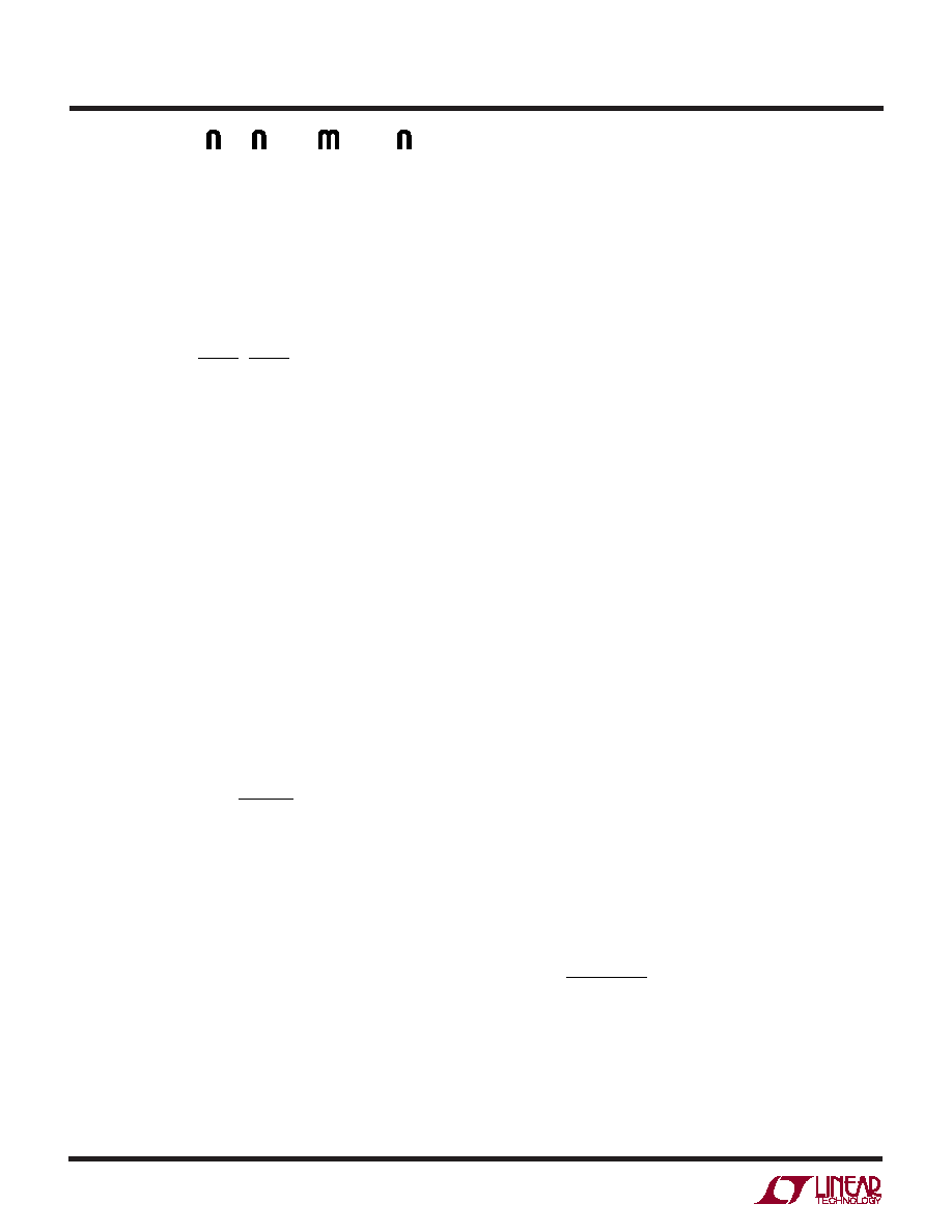 14 LTC1735 1735fc CIN Selection In continuous mode, the source current of the top N-channel MOSFET is a square wave of duty cycle VOUT/ VIN. To prevent large voltage transients, a low ESR input capacitor sized for the maximum RMS current must be used. The maximum RMS capacitor current is given by: II V V V V RMS O MAX OUT IN IN OUT ≅ () / –1 12 This formula has a maximum at VIN = 2VOUT, where IRMS = IO(MAX)/2. This simple worst case condition is com- monly used for design because even significant deviations do not offer much relief. Note that capacitor manufacturers’ ripple current ratings are often based on only 2000 hours of life. This makes it advisable to further derate the capacitor or to choose a capacitor rated at a higher temperature than required. Several capacitors may also be paralleled to meet size or height requirements in the design. Always consult the manufacturer if there is any question. COUT Selection The selection of COUT is primarily determined by the effective series resistance (ESR) to minimize voltage ripple. The output ripple ( ∆VOUT) in continuous mode is determined by: ∆∆ V I ESR fC OUT L OUT ≈+ 1 8 Where f = operating frequency, COUT = output capaci- tance and ∆IL = ripple current in the inductor. The output ripple is highest at maximum input voltage since ∆IL increases with input voltage. Typically, once the ESR requirement for COUT has been met, the RMS current rating generally far exceeds the IRIPPLE(P–P) requirement. With ∆IL= 0.3IOUT(MAX) and allowing 2/3 of the ripple due to ESR the output ripple will be less than 50mV at max VIN assuming: COUT required ESR < 2.2 RSENSE COUT > 1/(8fRSENSE) APPLICATIO S I FOR ATIO The first condition relates to the ripple current into the ESR of the output capacitance while the second term guaran- tees that the output capacitance does not significantly discharge during the operating frequency period due to ripple current. The choice of using smaller output capaci- tance increases the ripple voltage due to the discharging term but can be compensated for by using capacitors of very low ESR to maintain the ripple voltage at or below 50mV. The ITH pin OPTI-LOOP compensation compo- nents can be optimized to provide stable, high perfor- mance transient response regardless of the output capaci- tors selected. The selection of output capacitors for CPU or other appli- cations with large load current transients is primarily determined by the voltage tolerance specifications of the load. The resistive component of the capacitor, ESR, multiplied by the load current change plus any output voltage ripple must be within the voltage tolerance of the load (CPU). The required ESR due to a load current step is: RESR < ∆V/∆I where ∆I is the change in current from full load to zero load (or minimum load) and ∆V is the allowed voltage deviation (not including any droop due to finite capacitance). The amount of capacitance needed is determined by the maximum energy stored in the inductor. The capacitance must be sufficient to absorb the change in inductor current when a high current to low current transition occurs. The opposite load current transition is generally determined by the control loop OPTI-LOOP components, so make sure not to over compensate and slow down the response. The minimum capacitance to assure the inductors’ energy is adequately absorbed is: C LI VV OUT OUT > () () ∆ ∆ 2 2 where ∆I is the change in load current. Manufacturers such as Nichicon, United Chemi-Con and Sanyo can be considered for high performance through- hole capacitors. The OS-CON semiconductor electrolyte |
|
Enlace URL |
| ¿ALLDATASHEET es útil para Ud.? [ DONATE ] |
Todo acerca de Alldatasheet | Publicidad | Contáctenos | Política de Privacidad | Enlace a la hoja de datos | Intercambio de Enlaces | Lista de Fabricantes All Rights Reserved©Alldatasheet.com |
| Russian : Alldatasheetru.com | Korean : Alldatasheet.co.kr | Spanish : Alldatasheet.es | French : Alldatasheet.fr | Italian : Alldatasheetit.com Portuguese : Alldatasheetpt.com | Polish : Alldatasheet.pl | Vietnamese : Alldatasheet.vn Indian : Alldatasheet.in | Mexican : Alldatasheet.com.mx | British : Alldatasheet.co.uk | New Zealand : Alldatasheet.co.nz |
|
Family Site : ic2ic.com |
icmetro.com |
 Mexican ▼
 English
 Chinese
 German
 Japanese
 Russian
 Korean
 Spanish
 French
 Italian
 Portuguese
 Polish
 Vietnamese
 Indian
 Mexican
 British
 New Zealand