|
Motor de Búsqueda de Datasheet de Componentes Electrónicos |
|
|
Motor de Búsqueda de Datasheet de Componentes Electrónicos |
|
PCIMX515CJM6C Datasheet(PDF) 13 Page - Freescale Semiconductor, Inc |
|
|
|||||||||||||||||||||||||||||
PCIMX515CJM6C Datasheet(HTML) 13 Page - Freescale Semiconductor, Inc |
|
|
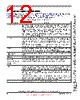
13 / 184 page  Features i.MX51 Applications Processors for Consumer and Industrial Products, Rev. 1 Freescale Semiconductor 13 Preliminary—Subject to Change Without Notice PMIC_INT_REQ When using the MC13892 power management IC, the PMIC_INT_REQ high-priority interrupt input on i.MX51 should be either floated or tied to NVCC_SRTC_POW with a 4.7 k Ω to 68 kΩ resistor. This avoids a continuous current drain on the real-time clock backup battery due to a 100 k Ω on-chip pull-up resistor. PMIC_INT_REQ is not used by the Freescale BSP (board support package) software. The BSP requires that the general-purpose INT output from the MC13892 be connected to i.MX51 GPIO input GPIO1_8 configured to cause an interrupt that is not high-priority. The original intent was for PMIC_INT_REQ to be connected to a circuit that detects when the battery is almost depleted. In this case, the I/O must be configured as alternate mode 0 (ALT0 = power fail). POR_B This cold reset negative logic input resets all modules and logic in the IC. Note: The POR_B input must be immediately asserted at power-up and remain asserted until after the last power rail is at its working voltage. RESET_IN_B This warm reset negative logic input resets all modules and logic except for the following: • Test logic (JTAG, IOMUXC, DAP) •SRTC • Memory repair – Configuration of memory repair per fuse settings • Cold reset logic of WDOG – Some WDOG logic is only reset by POR_B. See WDOG chapter in i.MX51 Reference Manual for details. RREFEXT Determines the reference current for the USB PHY bandgap reference. An external 6.04 k Ω 1% resistor to GND is required. SGND, SVCC, and SVDDGP These sense lines provide the ability to sense actual on-chip voltage levels on their respective supplies. SGND monitors differentials of the on-chip ground versus an external power source. SVCC monitors on-chip VCC, and SVDDGP monitors VDDGP. Freescale recommends connection of the SVCC and SVDDGP signals to the feedback inputs of switching power-supplies or to test points. STR This signal is reserved for Freescale manufacturing use. The user should float this signal. TEST_MODE TEST_MODE is for Freescale factory use only. This signal is internally connected to an on-chip pull-down device. Users must either float this signal or tie it to GND. VREF When using VREF with DDR-2 I/O, the nominal 0.9 V reference voltage must be half of the NVCC_EMI_DRAM supply. The user must tie VREF to a precision external resistor divider. Use a 1 k Ω 0.5% resistor to GND and a 1 kΩ 0.5% resistor to NVCC_EMI_DRAM. Shunt each resistor with a closely-mounted 0.1 µF capacitor. To reduce supply current, a pair of 1.5 k Ω 0.1% resistors can be used. Using resistors with recommended tolerances ensures the ± 2% VREF tolerance (per the DDR-2 specification) is maintained when four DDR-2 ICs plus the i.MX51 are drawing current on the resistor divider. Note: When VREF is used with mDDR this signal must be tied to GND. VREFOUT This signal determines the Triple Video DAC (TVDAC) reference voltage. The user must tie VREFOUT to an external 1.18 k Ω 1% resistor to GND. Table 3. Special Signal Considerations (continued) Signal Name Remarks |
|
Enlace URL |
| ¿ALLDATASHEET es útil para Ud.? [ DONATE ] |
Todo acerca de Alldatasheet | Publicidad | Contáctenos | Política de Privacidad | Enlace a la hoja de datos | Intercambio de Enlaces | Lista de Fabricantes All Rights Reserved©Alldatasheet.com |
| Russian : Alldatasheetru.com | Korean : Alldatasheet.co.kr | Spanish : Alldatasheet.es | French : Alldatasheet.fr | Italian : Alldatasheetit.com Portuguese : Alldatasheetpt.com | Polish : Alldatasheet.pl | Vietnamese : Alldatasheet.vn Indian : Alldatasheet.in | Mexican : Alldatasheet.com.mx | British : Alldatasheet.co.uk | New Zealand : Alldatasheet.co.nz |
|
Family Site : ic2ic.com |
icmetro.com |
 Mexican ▼
 English
 Chinese
 German
 Japanese
 Russian
 Korean
 Spanish
 French
 Italian
 Portuguese
 Polish
 Vietnamese
 Indian
 Mexican
 British
 New Zealand