|
Motor de Búsqueda de Datasheet de Componentes Electrónicos |
|
|
Motor de Búsqueda de Datasheet de Componentes Electrónicos |
|
ADP3330ARTZ-2.5-R7 Datasheet(PDF) 11 Page - Analog Devices |
|
|
|||||||||||||||||||||||||||||
ADP3330ARTZ-2.5-R7 Datasheet(HTML) 11 Page - Analog Devices |
|
|
11 / 16 page 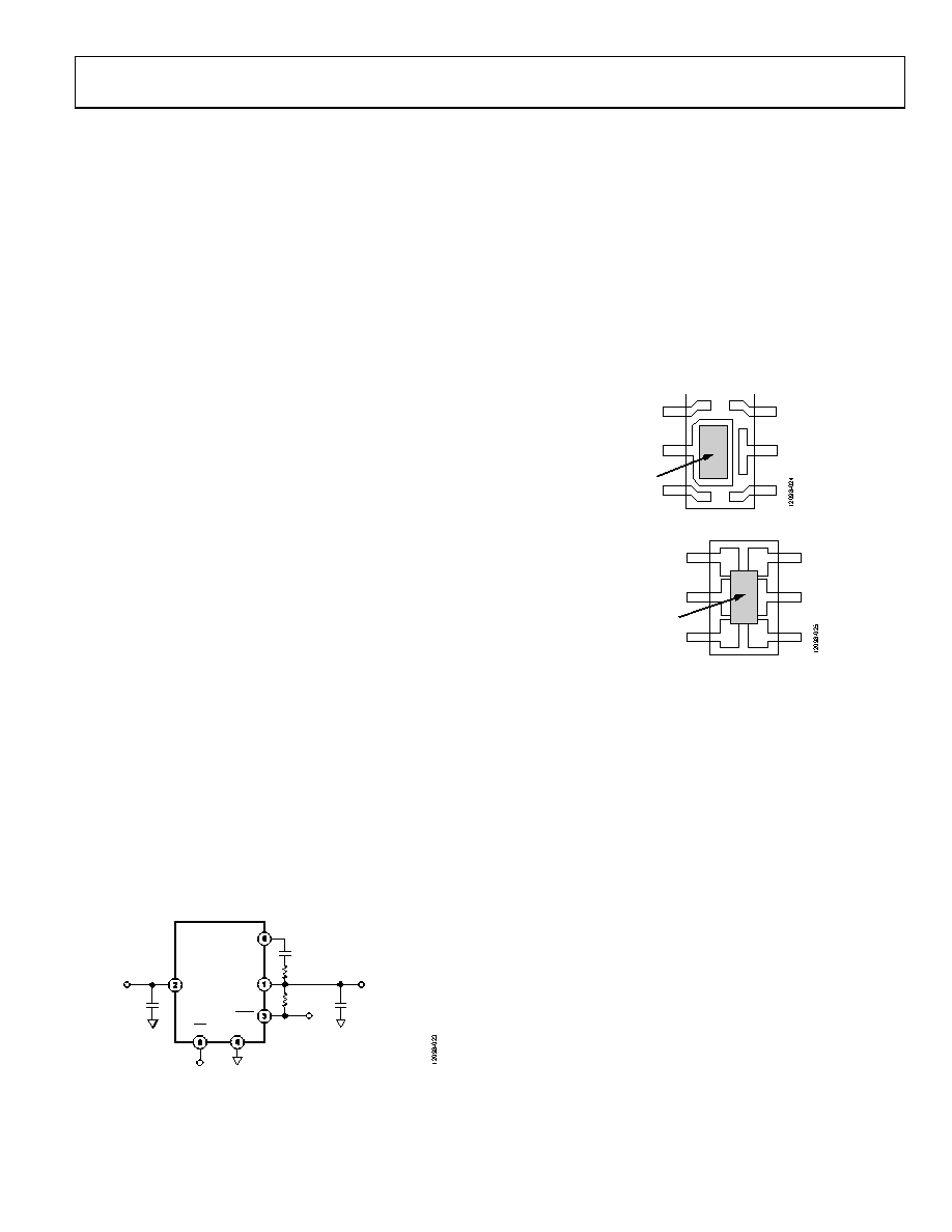 Data Sheet ADP3330 APPLICATIONS INFORMATION CAPACITOR SELECTION Output Capacitors As with any micropower device, output transient response is a function of the output capacitance. The ADP3330 is stable with a wide range of capacitor values, types, and ESR (anyCAP). A capacitor as low as 0.47 µF is all that is needed for stability; larger capacitors can be used if high output current surges are anticipated. The ADP3330 is stable with extremely low ESR capacitors (ESR ≈ 0), such as MLCC or OSCON. Note that the effective capacitance of some capacitor types may fall less than the minimum at cold temperature. Ensure that the capacitor provides more than 0.47 µF at minimum temperature. Input Bypass Capacitor An input bypass capacitor is not strictly required, but it is advisable in any application involving long input wires or high source impedance. Connecting a 0.47 µF capacitor from IN to GND reduces the sensitivity of the circuit to printed circuit board (PCB) layout. If a larger value output capacitor is used, a larger value input capacitor is also recommended. NOISE REDUCTION A noise reduction capacitor (CNR) can be used to further reduce the noise by 6 dB to 10 dB (see Figure 23). Low leakage capacitors in the 10 pF to 500 pF range provide the best performance. Carefully connect to this node to avoid noise pickup from external sources because the noise reduction pin (NR) is internally connected to a high impedance node. The pad connected to this pin must be as small as possible and long PCB traces are not recommended. When adding a noise reduction capacitor, use the following guidelines: • Maintain a minimum load current of 1 mA when not in shutdown. • For CNR values greater than 500 pF, add a 100 kΩ series resistor (RNR). It is important to note that as CNR increases, the turn on time is delayed. When CNR values are greater than 1 nF, this delay may be in the order of several milliseconds. Figure 23. Noise Reduction Circuit CHIP-ON-LEAD PACKAGE The ADP3330 uses a Chip-on-Lead package design (protected by U.S. Patent 5929514 A) to ensure the best thermal performance in the 6-lead SOT-23 footprint. In a standard 6-lead SOT-23 package, the majority of the heat flows out of the ground pin. The Chip-on-Lead package uses an electrically isolated die attachment that allows all pins to contribute to the heat conduction. This technique reduces the thermal resistance to 190°C/W on a 2-layer board as compared to >230°C/W for a standard SOT-23 lead frame. Figure 24 and Figure 25 show the difference between the standard 6-lead SOT-23 and the Chip-on- Lead lead frames. Figure 24. Normal 6-Lead SOT-23 Package Figure 25. Thermally Enhanced, Chip-on-Lead Package THERMAL OVERLOAD PROTECTION The ADP3330 is protected against damage due to excessive power dissipation by its thermal overload protection circuit, which limits the die temperature to a maximum of 165°C. Under extreme conditions, (that is, high ambient temperature and power dissipation) where die temperature starts to rise more than 165°C, the output current decreases until the die temperature has dropped to a safe level. The output current is restored when the die temperature is reduced. Current and thermal limit protections protect the device against accidental overload conditions. For normal operation, device power dissipation must be externally limited so that the junction temperatures do not exceed 125°C. VIN + – C1 0.47µF VOUT = 3.3V NR OUT GND IN C2 0.47µF + – ERR SD R1 330kΩ CNR RNR ADP3330-3 SILICON DIE SILICON DIE WITH ELECTRICALLY ISOLATED DIE ATTACH Rev. C | Page 11 of 16 |
|
|
Enlace URL |
| ¿ALLDATASHEET es útil para Ud.? [ DONATE ] |
Todo acerca de Alldatasheet | Publicidad | Contáctenos | Política de Privacidad | Enlace a la hoja de datos | Intercambio de Enlaces | Lista de Fabricantes All Rights Reserved©Alldatasheet.com |
| Russian : Alldatasheetru.com | Korean : Alldatasheet.co.kr | Spanish : Alldatasheet.es | French : Alldatasheet.fr | Italian : Alldatasheetit.com Portuguese : Alldatasheetpt.com | Polish : Alldatasheet.pl | Vietnamese : Alldatasheet.vn Indian : Alldatasheet.in | Mexican : Alldatasheet.com.mx | British : Alldatasheet.co.uk | New Zealand : Alldatasheet.co.nz |
|
Family Site : ic2ic.com |
icmetro.com |
 Mexican ▼
 English
 Chinese
 German
 Japanese
 Russian
 Korean
 Spanish
 French
 Italian
 Portuguese
 Polish
 Vietnamese
 Indian
 Mexican
 British
 New Zealand