|
Motor de Búsqueda de Datasheet de Componentes Electrónicos |
|
|
Motor de Búsqueda de Datasheet de Componentes Electrónicos |
|
L4969UR-E Datasheet(PDF) 16 Page - STMicroelectronics |
|
|
|||||||||||||||||||||||||||||
L4969UR-E Datasheet(HTML) 16 Page - STMicroelectronics |
|
|
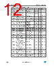
16 / 46 page  Functional description L4969UR-E, L4969URD-E 16/46 Doc ID 022587 Rev 2 3 Functional description 3.1 General features The L4969UR is a monolithic integrated circuit which provides all main functions for an automotive body CAN network. It features two independent regulated voltage supplies V1 and V2, an interrupt and reset logic with internal clock generator, Serial Interface and a low speed CAN-bus transceiver which is supplied by a separate third voltage regulator (V3). The device guarantees a clearly defined behavior in case of failure, to avoid permanent CAN bus errors. The device operates in four basic modes, with additional programming for V1 Standby modes in CTCR: 3.1.1 V1 output voltage The V1 regulator uses a DMOS transistor as an output stage. With this structure very low dropout voltage is obtained. The dropout operation of the standby regulator is maintained down to 4 V input supply voltage. The output voltage is regulated up to the transient input supply voltage of 40 V. With this feature no functional interruption due to overvoltage pulses is generated. The output 1 regulator is switched off in sleep mode. 3.1.2 V2 output voltage The V2 regulator uses the same output structure as the output 1 regulator except to being short circuit proof to VS. The V2 output can be switched on and off through a dedicated enable bit in the control register. In addition a tracking option can be enabled to allow V2 follow V1 with constant offset. This feature allows consistent A/D conversion inside the microcontroller (supplied by V1) when the converted signals are referenced to V2. The maximum voltage that can be applied to V2 is VS + 0.3 V up to a max VS of 40 V. Table 15. Operating mode description Mode V1 V2 V3 Timer/WDC CAN-IF Ityp LP1, LP0 (CTCR) Remarks Sleep #1 Off Off Off Off Standby 40µ x,x No Timer based wakeup Sleep #2 Off Off Off On (250Khz) Standby 80µ x,x Timer active based on tOSCslow Standby #1(1) On Off Off Off Standby 170µ 1,1 No Watchdog or Timer Standby #2(1) On Off Off On (250KHz) Standby 210µ 1,0 Watchdog or timer active based on tOSCslow Standby #3 On Off Off On (1MHz) Standby 440µ 0,0 Watchdog or timer activ, POR default RXOnly Off Off On On (1MHz) RX-Only 4mA x,x Active during Busactivity to filter ID, auto- matic fall back to Sleep when Bus idle Normal On On On On (1MHz) Normal 5mA x,x No Currents from CAN or Regulators 1. Note, that in order to enter either Standby #1 or Standby #2 the Startup-Watchdog has to be acknowledged, in Standby #1, the Window Watchdog has to be disabled as described in Chapter 2.5, to allow the decativation of the internal oscillator. |
|
Enlace URL |
| ¿ALLDATASHEET es útil para Ud.? [ DONATE ] |
Todo acerca de Alldatasheet | Publicidad | Contáctenos | Política de Privacidad | Enlace a la hoja de datos | Intercambio de Enlaces | Lista de Fabricantes All Rights Reserved©Alldatasheet.com |
| Russian : Alldatasheetru.com | Korean : Alldatasheet.co.kr | Spanish : Alldatasheet.es | French : Alldatasheet.fr | Italian : Alldatasheetit.com Portuguese : Alldatasheetpt.com | Polish : Alldatasheet.pl | Vietnamese : Alldatasheet.vn Indian : Alldatasheet.in | Mexican : Alldatasheet.com.mx | British : Alldatasheet.co.uk | New Zealand : Alldatasheet.co.nz |
|
Family Site : ic2ic.com |
icmetro.com |
 Mexican ▼
 English
 Chinese
 German
 Japanese
 Russian
 Korean
 Spanish
 French
 Italian
 Portuguese
 Polish
 Vietnamese
 Indian
 Mexican
 British
 New Zealand