 |
Motor de Búsqueda de Datasheet de Componentes Electrónicos |
|
|
Motor de Búsqueda de Datasheet de Componentes Electrónicos |
|
AD9880/PCB Datasheet(PDF) 21 Page - Analog Devices |
|
|
|||||||||||||||||||||||||||||
AD9880/PCB Datasheet(HTML) 21 Page - Analog Devices |
|
|
21 / 64 page 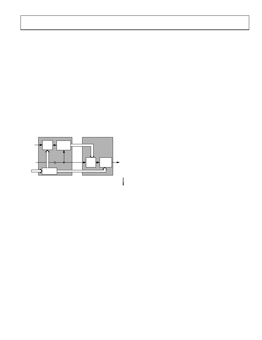 AD9880 Rev. 0 | Page 21 of 64 A programming example and register settings for several common conversions are listed in the Color Space Converter (CSC) Common Settings. For a detailed functional description and more programming examples, please refer to the application note AN-795, AD9880 Color space Converter User's Guide. AUDIO PLL SETUP Data contained in the Audio Infoframes among other registers define for the AD9880 HDMI receiver not only the type of audio, but the sample frequency. It also contains information about the N and CTS values used to recreate the clock. With this information it is possible to regenerate the audio sampling frequency. The audio clock is regenerated by dividing the 20-bit CTS value into the TMDS clock, then multiplying by the 20-bit N value. This yields a multiple of the fs (sampling frequency) of either 128 × fs or 256 × fs. It is possible for this to be specified up to 1024 × fs. SINK DEVICE SOURCE DEVICE 1N AND CTS VALUES ARE TRANSMITTED USING THE "AUDIO CLOCK REGENERATION" PACKET. VIDEO CLOCK IS TRANSMITTED ON TMDS CLOCK CHANNEL. 128 × f S N VIDEO CLOCK 128 × f S TMDS CLOCK N1 CTS1 DIVIDE BY N CYCLE TIME COUNTER REGISTER N DIVIDE BY CTS MUTIPLY BY N Figure 14. N and CTS for Audio Clock AUDIO BOARD LEVEL MUTING The audio can be muted through the Infoframes or locally via the serial bus registers. This can be controlled with Register R0x57, Bits [7:4]. AVI Infoframes Contained within the HDMI TMDS transmission are Infoframes containing specific information for the monitor such as • Audio information o 2 to 8 channels of audio identified o Audio coding o Audio sampling frequency • Speaker placement • N and CTS values (for reconstruction of the audio) • Muting • Source information o CD o SACD o DVD • Video information o Video ID Code (per CEA861B) o Color space o Aspect ratio o Horizontal and vertical bar information o MPEG frame information (I, B, or P frame) • Vendor (transmitter source) information o Vendor name and product model This information is the fundamental difference between DVI and HDMI transmissions and is located in read-only registers R0x5A to R0xEE. In addition to this information, registers are provided that indicate that new information has been received. Registers with addresses ending in 0xX7 or 0xXF beginning at R0x87 contain the new data flags (NDF) information. All of these registers contain the same information and all are reset once any of them are read. Although there is no external interrupt signal, it is very straightforward for the user to read any of these registers and see if there is new information to be processed. TIMING DIAGRAMS The following timing diagrams show the operation of the AD9880.The output data clock signal is created so that its rising edge always occurs between data transitions and can be used to latch the output data externally. There is a pipeline in the AD9880, which must be flushed before valid data becomes available. This means six data sets are presented before valid data is available. |
|
Enlace URL |
| ¿ALLDATASHEET es útil para Ud.? [ DONATE ] |
Todo acerca de Alldatasheet | Publicidad | Contáctenos | Política de Privacidad | Enlace a la hoja de datos | Intercambio de Enlaces | Lista de Fabricantes All Rights Reserved©Alldatasheet.com |
| Russian : Alldatasheetru.com | Korean : Alldatasheet.co.kr | Spanish : Alldatasheet.es | French : Alldatasheet.fr | Italian : Alldatasheetit.com Portuguese : Alldatasheetpt.com | Polish : Alldatasheet.pl | Vietnamese : Alldatasheet.vn Indian : Alldatasheet.in | Mexican : Alldatasheet.com.mx | British : Alldatasheet.co.uk | New Zealand : Alldatasheet.co.nz |
|
Family Site : ic2ic.com |
icmetro.com |
 Mexican ▼
 English
 Chinese
 German
 Japanese
 Russian
 Korean
 Spanish
 French
 Italian
 Portuguese
 Polish
 Vietnamese
 Indian
 Mexican
 British
 New Zealand


