 |
Motor de Búsqueda de Datasheet de Componentes Electrónicos |
|
|
Motor de Búsqueda de Datasheet de Componentes Electrónicos |
|
ADRF6620ACPZ-R7 Datasheet(PDF) 39 Page - Analog Devices |
|
|
|||||||||||||||||||||||||||||
ADRF6620ACPZ-R7 Datasheet(HTML) 39 Page - Analog Devices |
|
|
39 / 52 page 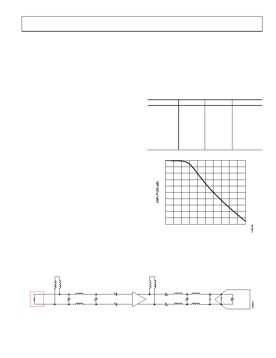 Data Sheet ADRF6620 Rev. 0 | Page 39 of 52 ADC INTERFACING The integrated IF DGA of the ADRF6620 provides variable and sufficient drive capability for both buffered and unbuffered ADCs. It also provides isolation between the sampling edges of the ADC and the mixer core. As result, only an antialiasing filter is required when interfacing with an ADC. The ADRF6620 is optimized for use in cellular base station digital predistortion (DPD) systems. Predistortion is used to improve the linearity of transmitter power amplifiers (PA). Because the input signal to the DPD path is the known transmitted signal, the hardware specifications are not typically as stringent as the main receive path. The signal-to-noise ratio (SNR) of the ADC is not paramount, due to the autocorrelation with the known transmitted signal. For this reason, lower resolution ADCs are usually adequate, and 11-bit to 14-bit resolution typically suffices. A more critical consideration is the analog bandwidth of the converter. Traditional DPD systems require 3× to 5× the transmit bandwidth. Therefore, for a 100 MHz Tx bandwidth, the DPD bandwidth must be at least 500 MHz for fifth-order correction. The AD9434 complements the ADRF6620 very well in a DPD design. The AD9434 is a 12-bit, 370 MSPS/500 MSPS buffered ADC. Its full power analog bandwidth is 1 GHz, making it wide enough for fifth-order correction with substantial margin. The sampling rate of the AD9434 is insufficient in satisfying the sampling theorem; however, this may be acceptable in DPD applications where undersampling is often permissible. Because the receive signal in the DPD path is the known transmitted signal, the desired signal and its aliases are clearly distinguished. The antialiasing filter resides between the ADRF6620 and the AD9434. Because aliasing is common practice in a DPD receive chain, the antialiasing filter requirements can be relaxed. A second-order or third-order filter is sufficient in reducing the high frequency noise from folding back into the band of interest. When designing the antialiasing filter, it is important to consider the output impedance of the IF DGA of the ADRF6620 and the input impedance of the AD9434. The differential resistance of the AD9434 is 1 kΩ, and the parallel capacitance is 1.3 pF. For the matched load condition, where the IF DGA is optimized for gain and linearity, load the IF DGA with 150 Ω. To do this, place a 176 Ω resistor in parallel with the input of the ADC. The parallel combination of the 176 Ω with the 1 kΩ of the ADC input impedance results in an equivalent 150 Ω differential output load as seen by the IF DGA of the ADRF6620. In addition, the input capacitance of the AD9434 can be used as the fourth pole of the antialiasing filter. The final schematic design is shown in Figure 99. The antialiasing filter is maximally flat, with a pass- band bandwidth of 500 MHz. Table 19 shows the component values for the antialiasing filter design for DPD. Figure 98 shows the simulated antialiasing filter design. Table 19. Component Values for 500 MHz Antialiasing Filter Design Parameter Value Type Manufacturer L1 = L2 470 nH 0805CS Coilcraft C1 DNP GRM15 Murata L3 = L4 39 nH 0805CS Coilcraft C2 DNP GRM15 Murata L5 = L6 1 µH 0805LS Coilcraft L7 = L8 15 nH 0805CS Coilcraft C3 2.7 pF GRM15 Murata L9 = L10 27 nH 0805CS Coilcraft –50 –45 –40 –35 –30 –25 –20 –15 –10 –5 0 0 200 400 600 800 1000 1200 1400 1600 1800 2000 FREQUENCY (MHz) Figure 98. Simulated Antialiasing Filter Design AD9434 255Ω ADRF6620 MIXER OUTPUT +5V +5V ADRF6620 IF AMP L1 L2 L5 L6 L3 L4 L9 L10 L7 L8 C1 C2 C3 1kΩ 1.3pF 88Ω 88Ω 0.1µF 0.1µF 0.1µF 0.1µF Figure 99. ADRF6620 Interface to the AD9434 |
|
Enlace URL |
| ¿ALLDATASHEET es útil para Ud.? [ DONATE ] |
Todo acerca de Alldatasheet | Publicidad | Contáctenos | Política de Privacidad | Enlace a la hoja de datos | Intercambio de Enlaces | Lista de Fabricantes All Rights Reserved©Alldatasheet.com |
| Russian : Alldatasheetru.com | Korean : Alldatasheet.co.kr | Spanish : Alldatasheet.es | French : Alldatasheet.fr | Italian : Alldatasheetit.com Portuguese : Alldatasheetpt.com | Polish : Alldatasheet.pl | Vietnamese : Alldatasheet.vn Indian : Alldatasheet.in | Mexican : Alldatasheet.com.mx | British : Alldatasheet.co.uk | New Zealand : Alldatasheet.co.nz |
|
Family Site : ic2ic.com |
icmetro.com |
 Mexican ▼
 English
 Chinese
 German
 Japanese
 Russian
 Korean
 Spanish
 French
 Italian
 Portuguese
 Polish
 Vietnamese
 Indian
 Mexican
 British
 New Zealand


