|
Motor de Búsqueda de Datasheet de Componentes Electrónicos |
|
|
Motor de Búsqueda de Datasheet de Componentes Electrónicos |
|
ADE7758 Datasheet(PDF) 50 Page - Analog Devices |
|
|
|||||||||||||||||||||||||||||
ADE7758 Datasheet(HTML) 50 Page - Analog Devices |
|
|
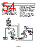
50 / 72 page  ADE7758 Data Sheet Rev. E | Page 50 of 72 Step 5: Set the LENERGY bit, MASK[12] (0x18), to Logic 1 to enable the interrupt signaling the end of the line cycle accumulation. Step 6: Set the test system for ITEST, VNOM, and unity power factor (calibrate watt and VA simultaneously and first). Step 7: Read the FREQ (0x10) register if the line frequency is unknown. Step 8: Reset the interrupt status register by reading RSTATUS (0x1A). Step 9: Read all six xWATTHR (0x01 to 0x03) and xVAHR (0x07 to 0x09) energy registers after the LENERGY interrupt and store the values. Step 9a: Calculate the values to be written to xWG registers according to the following equations: () WDIV APCFNUM APCFDEN AccumTime θ cos V I MC WATTHR NOM TEST EXPECTED 1 3600 1000 4 × × × × × × × × = (60) where AccumTime is [] Selected Phases of No. Frequency Line : LINECYC × × 2 0 15 (61) where: MC is the meter constant. θ is the angle between the current and voltage. Line Frequency is known or calculated from the FREQ[11:0] register. With the FREQ[11:0] register configured for line period measurements, the line frequency is calculated with Equation 62. 6 - 10 9.6 0] : [11 1 × × = FREQ Frequency Line (62) No. of Phases Selected is the number of ZXSEL bits set to Logic 1 in LCYCMODE (0x17). Then, xWG is calculated as 12 2 1 × ⎟⎟ ⎠ ⎞ ⎜⎜ ⎝ ⎛ − = MEASURED EXPECTED WATTHR WATTHR xWG (63) Step 9b: Calculate the values to be written to the xVAG registers according to the following equation: VADIV VARCFNUM VARCFDEN AccumTime V I MC VAHR NOM TEST EXPECTED 1 3600 1000 4 × × × × × × × = (64) 12 2 1 × ⎟⎟ ⎠ ⎞ ⎜⎜ ⎝ ⎛ − = MEASURED EXPECTED VAHR VAHR xVAG Step 10: Write to xWG and xVAG. Step 11: Set the test system for ITEST, VNOM, and zero power factor inductive to calibrate VAR gain. Step 12: Repeat Step 7. Step 13: Read the xVARHR (0x04 to 0x06) after the LENERGY interrupt and store the values. Step 14: Calculate the values to be written to the xVARG registers (to adjust VARCF to the expected value). () VARDIV VARCFNUM VARCFDEN AccumTime θ sin V I MC VARHR NOM TEST EXPECTED 1 3600 1000 4 × × × × × × × × = (65) 12 2 1 × ⎟⎟ ⎠ ⎞ ⎜⎜ ⎝ ⎛ − = MEASURED EXPECTED VARHR VARHR xVARG Step 15: Write to xVARG. Step 16: Calculate the Wh/LSB, VARh/LSB, and VAh/LSB constants. () xWATTHR AccumTime θ cos V I LSB Wh NOM TEST × × × × = 3600 (66) xVAHR AccumTime V I LSB VAh NOM TEST × × × = 3600 (67) () xVARHR AccumTime θ sin V I LSB VARh NOM TEST × × × × = 3600 (68) Example: Watt Gain Calibration Using Line Accumulation This example shows only Phase A watt calibration. The steps outlined in the Gain Calibration Using Line Accumulation section show how to calibrate watt, VA, and VAR. All three phases can be calibrated simultaneously because there are nine energy registers. For this example, ITEST = 10 A, VNOM = 220 V, Power Factor = 1, Frequency = 50 Hz, LINECYC (0x1C) is set to 0x800, and MC = 3200 imp/kWhr. |
|
Enlace URL |
| ¿ALLDATASHEET es útil para Ud.? [ DONATE ] |
Todo acerca de Alldatasheet | Publicidad | Contáctenos | Política de Privacidad | Enlace a la hoja de datos | Intercambio de Enlaces | Lista de Fabricantes All Rights Reserved©Alldatasheet.com |
| Russian : Alldatasheetru.com | Korean : Alldatasheet.co.kr | Spanish : Alldatasheet.es | French : Alldatasheet.fr | Italian : Alldatasheetit.com Portuguese : Alldatasheetpt.com | Polish : Alldatasheet.pl | Vietnamese : Alldatasheet.vn Indian : Alldatasheet.in | Mexican : Alldatasheet.com.mx | British : Alldatasheet.co.uk | New Zealand : Alldatasheet.co.nz |
|
Family Site : ic2ic.com |
icmetro.com |
 Mexican ▼
 English
 Chinese
 German
 Japanese
 Russian
 Korean
 Spanish
 French
 Italian
 Portuguese
 Polish
 Vietnamese
 Indian
 Mexican
 British
 New Zealand