|
Motor de Búsqueda de Datasheet de Componentes Electrónicos |
|
|
Motor de Búsqueda de Datasheet de Componentes Electrónicos |
|
ADE7758 Datasheet(PDF) 51 Page - Analog Devices |
|
|
|||||||||||||||||||||||||||||
ADE7758 Datasheet(HTML) 51 Page - Analog Devices |
|
|
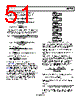
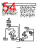
51 / 72 page  Data Sheet ADE7758 Rev. E | Page 51 of 72 To set APCFNUM (0x45) and APCFDEN (0x46) to the calculated value to perform a coarse adjustment on the imp/kW-hr ratio, use Equation 45 to Equation 47. kHz 5415 . 0 130 10 500 220 kH 16 = × × = z APCF NOMINAL () Hz 1.956 cos 3600 1000 220 10 3200 = θ × × × × = EXPECTED APCF 277 Hz 956 . 1 Hz 5 . 541 INT = ⎟ ⎟ ⎠ ⎞ ⎜ ⎜ ⎝ ⎛ = APCFDEN Under the test conditions above, the AWATTHR register value is 15559d after the LENERGY interrupt. Using Equation 60 and Equation 61, the value to be written to AWG is −199d, 0xF39. [] Selected Phases of No. FREQ : LINECYC AccumTime × × × × = −6 10 6 . 9 ] 0 : 11 [ 1 2 0 15 6.832128s 3 10 6 . 9 2085 1 2 800 0 6 = × × × × = − x AccumTime 14804 1 1 277 3600 1000 832 . 6 1 220 10 3200 4 = × × × × × × × × = EXPECTED WATTHR 0xF39 –199 –198.87640 2 1 15559 14804 12 = = = × ⎟ ⎠ ⎞ ⎜ ⎝ ⎛ − = xWG Using Equation 66, the Wh/LSB constant is 0 0.000282 14804 3600 832 . 6 220 10 = × × × = LSB Wh Phase Calibration Using Line Accumulation The ADE7758 includes a phase calibration register on each phase to compensate for small phase errors. Large phase errors should be compensated by adjusting the antialiasing filters. The ADE7758 phase calibration is a time delay with different weights in the positive and negative direction (see the Phase Compensation section). Because a current transformer is a source of phase error, a fixed nominal value can be decided on to load into the xPHCAL (0x3F to 0x41) registers at power-up. During calibration, this value can be adjusted for CT-to-CT error. Figure 83 shows the steps involved in calibrating the phase using the line accumulation mode. STEP 1 SET LCYCMODE, LINECYC AND MASK REGISTERS STEP 2 SET UP SYSTEM FOR ITEST,VNOM,PF = 0.5, INDUCTIVE STEP 3 RESET STATUS REGISTER STEP 4 READ ALL xWATTHR REGISTERS AFTER LENERGY INTERRUPT STEP 5 CALCULATE PHASE ERROR IN DEGREES FOR ALL PHASES STEP 6 CALCULATE AND WRITE TO ALL xPHCAL REGISTERS Figure 83. Phase Calibration Using Line Accumulation Step 1: If the values were changed after gain calibration, Step 1, Step 3, and Step 4 from the gain calibration should be repeated to configure the LCYCMODE and LINECYC registers. Step 2: Set the test system for ITEST, VNOM, and 0.5 power factor inductive. Step 3: Reset the interrupt status register by reading RSTATUS (0x1A). Step 4: The xWATTHR registers should be read after the LENERGY interrupt. Measure the percent error in the energy register readings (AWATTHR, BWATTHR, and CWATTHR) compared to the energy register readings at unity power factor (after gain calibration) using Equation 69. The readings at unity power factor should have been repeated after the gain calibration and stored for use in the phase calibration routine. 2 2 – 1 PF 1 PF 5 PF = = = = xWATTHR xWATTHR xWATTHR Error (69) Step 5: Calculate the Phase Error in degrees using the equation () ⎟ ⎠ ⎞ ⎜ ⎝ ⎛ = ° 3 – Error Arcsin Error Phase (70) Step 6: Calculate xPHCAL and write to the xPHCAL registers (0x3F to 0x41). ° × × × = 360 1 ) ( 1 _ _ 1 s Period Line Weight LSB PHCAL Error Phase xPHCAL (71) where PHCAL_LSB_Weight is 1.2 μs if the %Error is negative or 2.4 μs if the %Error is positive (see the Phase Compensation section). |
|
Enlace URL |
| ¿ALLDATASHEET es útil para Ud.? [ DONATE ] |
Todo acerca de Alldatasheet | Publicidad | Contáctenos | Política de Privacidad | Enlace a la hoja de datos | Intercambio de Enlaces | Lista de Fabricantes All Rights Reserved©Alldatasheet.com |
| Russian : Alldatasheetru.com | Korean : Alldatasheet.co.kr | Spanish : Alldatasheet.es | French : Alldatasheet.fr | Italian : Alldatasheetit.com Portuguese : Alldatasheetpt.com | Polish : Alldatasheet.pl | Vietnamese : Alldatasheet.vn Indian : Alldatasheet.in | Mexican : Alldatasheet.com.mx | British : Alldatasheet.co.uk | New Zealand : Alldatasheet.co.nz |
|
Family Site : ic2ic.com |
icmetro.com |
 Mexican ▼
 English
 Chinese
 German
 Japanese
 Russian
 Korean
 Spanish
 French
 Italian
 Portuguese
 Polish
 Vietnamese
 Indian
 Mexican
 British
 New Zealand