|
Motor de Búsqueda de Datasheet de Componentes Electrónicos |
|
|
Motor de Búsqueda de Datasheet de Componentes Electrónicos |
|
ADE7758 Datasheet(PDF) 52 Page - Analog Devices |
|
|
|||||||||||||||||||||||||||||
ADE7758 Datasheet(HTML) 52 Page - Analog Devices |
|
|
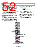
52 / 72 page  ADE7758 Data Sheet Rev. E | Page 52 of 72 If it is not known, the line period is available in the ADE7758 frequency register, FREQ (0x10). To configure line period measurement, select the phase for period measurement in the MMODE[1:0] and set LCYCMODE[7]. Equation 72 shows how to determine the value that needs to be written to xPHCAL using the period register measurement. ° × × = 360 ] 0 : 11 [ _ _ μs 6 . 9 FREQ Weight LSB PHCAL Error Phase xPHCAL (72) Example: Phase Calibration Using Line Accumulation This example shows only Phase A phase calibration. All three PHCAL registers can be calibrated simultaneously using the same method. For this example, ITEST = 10 A, VNOM = 220 V, power factor = 0.5 inductive, and frequency = 50 Hz. Also, LINECYC = 0x800. With ITEST, VNOM, and 0.5 inductive power factor, the example ADE7758 meter shows 7318d in the AWATTHR (0x01) register. 14804d in the AWATTHR register. This is equivalent to −1.132% error. % 132 . 1 01132 . 0 2 14804 2 14804 – 7318 − = − = = Error The Phase Error in degrees using Equation 66 is 0.374°. () ° = ⎟ ⎠ ⎞ ⎛ − 01132 . 0 ⎜ ⎝ = ° 374 . 0 3 sin –Arc Error Phase Using Equation 72, the value written to APHCAL (0x3F), if at 50 Hz, the FREQ (0x10) register = 2085d, is 17d. Note that a PHCAL_LSB_Weight of 1.2 μs is used because the %Error is negative. 11 x 0 17 360 2085 2 . 1 6 . 9 374 . 0 = = × × ° = APHCAL For unity power factor (after gain calibration), the meter shows STEP 1 SET MMODE, LCYCMODE, LINECYC AND MASK REGISTERS STEP 2 SET UP SYSTEM FOR IMIN,VNOM @PF = 1 STEP 3 RESET STATUS REGISTER STEP 4 READ ALL xWATTHR REGISTERS AFTER LENERGY INTERRUPT END FOR STEP 8 READ ALL xVARHR AFTER LENERGY INTERRUPT FOR STEP 8, CALCULATE xVAROS FOR ALL PHASES STEP 5 CALCULATE xWATTOS FOR ALL PHASES FOR STEP 8, WRITE TO ALL xVAROS REGISTERS STEP 6 WRITE TO ALL xWATTOS REGISTERS STEP 7 SET UP SYSTEM FOR ITEST,VNOM @ PF = 0, INDUCTIVE STEP 8 REPEAT STEP 3 TO STEP 8 FOR xVARHR, xVAROS CALIBRATION Figure 84. Power Offset Calibration Using Line Accumulation |
|
Enlace URL |
| ¿ALLDATASHEET es útil para Ud.? [ DONATE ] |
Todo acerca de Alldatasheet | Publicidad | Contáctenos | Política de Privacidad | Enlace a la hoja de datos | Intercambio de Enlaces | Lista de Fabricantes All Rights Reserved©Alldatasheet.com |
| Russian : Alldatasheetru.com | Korean : Alldatasheet.co.kr | Spanish : Alldatasheet.es | French : Alldatasheet.fr | Italian : Alldatasheetit.com Portuguese : Alldatasheetpt.com | Polish : Alldatasheet.pl | Vietnamese : Alldatasheet.vn Indian : Alldatasheet.in | Mexican : Alldatasheet.com.mx | British : Alldatasheet.co.uk | New Zealand : Alldatasheet.co.nz |
|
Family Site : ic2ic.com |
icmetro.com |
 Mexican ▼
 English
 Chinese
 German
 Japanese
 Russian
 Korean
 Spanish
 French
 Italian
 Portuguese
 Polish
 Vietnamese
 Indian
 Mexican
 British
 New Zealand