|
Motor de Búsqueda de Datasheet de Componentes Electrónicos |
|
|
Motor de Búsqueda de Datasheet de Componentes Electrónicos |
|
ADE7758 Datasheet(PDF) 19 Page - Analog Devices |
|
|
|||||||||||||||||||||||||||||
ADE7758 Datasheet(HTML) 19 Page - Analog Devices |
|
|
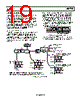
19 / 72 page  Data Sheet ADE7758 Rev. E | Page 19 of 72 CURRENT CHANNEL ADC Figure 41 shows the ADC and signal processing path for the input IA of the current channels (same for IB and IC). In waveform sampling mode, the ADC outputs are signed twos complement 24-bit data-words at a maximum of 26.0 kSPS (thousand samples per second). With the specified full-scale analog input signal of ±0.5 V, the ADC produces its maximum output code value (see Figure 41). This diagram shows a full- scale voltage signal being applied to the differential inputs IAP and IAN. The ADC output swings between 0xD7AE14 (−2,642,412) and 0x2851EC (+2,642,412). Current Channel Sampling The waveform samples of the current channel can be routed to the WFORM register at fixed sampling rates by setting the WAVSEL[2:0] bit in the WAVMODE register to 000 (binary) (see Table 20). The phase in which the samples are routed is set by setting the PHSEL[1:0] bits in the WAVMODE register. Energy calculation remains uninterrupted during waveform sampling. When in waveform sample mode, one of four output sample rates can be chosen by using Bit 5 and Bit 6 of the WAVMODE register (DTRT[1:0]). The output sample rate can be 26.04 kSPS, 13.02 kSPS, 6.51 kSPS, or 3.25 kSPS. By setting the WFSM bit in the interrupt mask register to Logic 1, the interrupt request output IRQ goes active low when a sample is available. The timing is shown in . The 24-bit waveform samples are transferred from the one byte (8-bits) at a time, with the most significant byte shifted out first. Figure 40 ADE7758 READ FROM WAVEFORM 0 SGN CURRENT CHANNEL DATA–24 BITS 0x12 SCLK DIN DOUT IRQ Figure 40. Current Channel Waveform Sampling The interrupt request output IRQ stays low until the interrupt routine reads the reset status register (see the section). Interrupts DIGITAL INTEGRATOR1 GAIN[7] ADC REFERENCE ACTIVE AND REACTIVE POWER CALCULATION WAVEFORM SAMPLE REGISTER CURRENT RMS (IRMS) CALCULATION IAP IAN PGA1 VIN GAIN[4:3] 2.42V, 1.21V, 0.6V GAIN[1:0] ×1, ×2, ×4 ANALOG INPUT RANGE VIN 0V 0.5V/GAIN 0.25V/GAIN 0.125V/GAIN ADC OUTPUT WORD RANGE CHANNEL 1 (CURRENT WAVEFORM) DATA RANGE 0xD7AE14 0x000000 0x2851EC 50Hz CHANNEL 1 (CURRENT WAVEFORM) DATA RANGE AFTER INTEGRATOR (50Hz AND AIGAIN[11:0] = 0x000) 0xCB2E48 0x000000 0x34D1B8 60Hz CHANNEL 1 (CURRENT WAVEFORM) DATA RANGE AFTER INTEGRATOR (60Hz AND AIGAIN[11:0] = 0x000) 0xD4176D 0x000000 0x2BE893 HPF 1WHEN DIGITAL INTEGRATOR IS ENABLED, FULL-SCALE OUTPUT DATA IS ATTENUATED DEPENDING ON THE SIGNAL FREQUENCY BECAUSE THE INTEGRATOR HAS A –20dB/DECADE FREQUENCY RESPONSE. WHEN DISABLED, THE OUTPUT WILL NOT BE FURTHER ATTENUATED. Figure 41. Current Channel Signal Path |
|
Enlace URL |
| ¿ALLDATASHEET es útil para Ud.? [ DONATE ] |
Todo acerca de Alldatasheet | Publicidad | Contáctenos | Política de Privacidad | Enlace a la hoja de datos | Intercambio de Enlaces | Lista de Fabricantes All Rights Reserved©Alldatasheet.com |
| Russian : Alldatasheetru.com | Korean : Alldatasheet.co.kr | Spanish : Alldatasheet.es | French : Alldatasheet.fr | Italian : Alldatasheetit.com Portuguese : Alldatasheetpt.com | Polish : Alldatasheet.pl | Vietnamese : Alldatasheet.vn Indian : Alldatasheet.in | Mexican : Alldatasheet.com.mx | British : Alldatasheet.co.uk | New Zealand : Alldatasheet.co.nz |
|
Family Site : ic2ic.com |
icmetro.com |
 Mexican ▼
 English
 Chinese
 German
 Japanese
 Russian
 Korean
 Spanish
 French
 Italian
 Portuguese
 Polish
 Vietnamese
 Indian
 Mexican
 British
 New Zealand