|
Motor de Búsqueda de Datasheet de Componentes Electrónicos |
|
|
Motor de Búsqueda de Datasheet de Componentes Electrónicos |
|
ADE7758 Datasheet(PDF) 53 Page - Analog Devices |
|
|
|||||||||||||||||||||||||||||
ADE7758 Datasheet(HTML) 53 Page - Analog Devices |
|
|
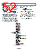
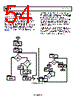
53 / 72 page  Data Sheet ADE7758 Rev. E | Page 53 of 72 Power Offset Calibration Using Line Accumulation Power offset calibration should be used for outstanding performance over a wide dynamic range (1000:1). Calibration of the power offset is done at or close to the minimum current. The ADE7758 has power offset registers for watts and VAR, xWATTOS (0x39 to 0x3B) and xVAROS (0x3C to 0x3E). Offsets in the VA measurement are compensated by adjusting the rms offset registers (see the Calibration of IRMS and VRMS Offset section). More line cycles could be required at the minimum current to minimize the effect of quantization error on the offset calibration. For example, if a current of 40 mA results in an active energy accumulation of 113 after 2000 half line cycles, one LSB variation in this reading represents an 0.8% error. This measurement does not provide enough resolution to calibrate out a <1% offset error. However, if the active energy is accumulated over 37,500 half line cycles, one LSB variation results in 0.05% error, reducing the quantization error. Figure 84 shows the steps to calibrate the power offsets using the line accumulation mode. Step 1: If the values change after gain calibration, Step 1, Step 3, and Step 4 from the gain calibration should be repeated to configure the LCYCMODE, LINECYC, and MASK registers. Select Phase A, Phase B, or Phase C for a line period measure- ment with the FREQSEL[1:0] bits in the MMODE register (0x14). For example, clearing Bit 1 and Bit 0 selects Phase A for line period measurement. Step 2: Set the test system for IMIN, VNOM, and unity power factor. Step 3: Reset the interrupt status register by reading RSTATUS (0x1A). Step 4: Read all xWATTHR energy registers (0x01 to 0x03) after the LENERGY interrupt and store the values. Step 4a: If it is not known, the line period is available in the ADE7758 frequency register, FREQ (0x10). To configure line period measurement, select the phase for period measurement in the MMODE[1:0] and set LCYCMODE[7]. Step 5: Calculate the value to be written to the xWATTOS registers according to the following equations: TEST MIN MIN ITEST IMIN I TEST I I I I LINECYC LINECYC xWATTHR I xWATTHR Offset TEST MIN – – × ⎟⎟ ⎠ ⎞ ⎜⎜ ⎝ ⎛ × × = (73) [] 29 2 4 0 : 11 × × × = CLKIN AccumTime Offset xWATTOS (74) where: AccumTime is defined in Equation 61. is the value in the energy register at ITEST. is the value in the energy register at IMIN. LINECYCIMIN is the number of line cycles accumulated at IMIN. LINECYCIMAX is the number of line cycles accumulated at IMAX. TEST I xWATTHR MIN I xWATTHR Step 6: Write to all xWATTOS registers (0x39 to 0x3B). Step 7: Set the test system for IMIN, VNOM, and zero power factor inductive to calibrate VAR gain. Step 8: Repeat Steps 3, 4, and 5. Step 9: Calculate the value written to the xVAROS registers according to the following equations: TEST MIN MIN ITEST IMIN I TEST I I I I LINECYC LINECYC xVARHR I xVARHR Offset TEST MIN – – × ⎟⎟ ⎠ ⎞ ⎜⎜ ⎝ ⎛ × × = (75) 26 2 202 ] 0 : 11 [ 4 0] : [11 × × × × = FREQ CLKIN AccumTime Offset xVAROS (76) where the FREQ[11:0] register is configured for line period readings. Example: Power Offset Calibration Using Line Accumulation This example only shows Phase A of the phase active power offset calibration. Both active and reactive power offset for all phases can be calibrated simultaneously using the method explained in the Power Offset Calibration Using Line Accumulation section. For this example, IMIN = 50 mA, ITEST = 10 A, VNOM = 220 V, VFULLSCALE = 500 V, IFULLSCALE = 130 A, MC = 3200 impulses/kWh, Power Factor = 1, Frequency = 50 Hz, and CLKIN = 10 MHz. Also, LINECYCITEST = 0x800 and LINECYCIMIN = 0x4000. After accumulating over 0x800 line cycles for gain calibration at ITEST, the example ADE7758 meter shows 14804d in the AWATTHR (0x01) register. At IMIN, the meter shows 592d in the AWATTHR register. By using Equation 73, this is equivalent to 0.161 LSBs of offset; therefore, using Equation 61 and Equation 74, the value written to AWATTOS is 0d. 0.16 10 – 0.05 0.05 0x800 0x4000 14804 – 10 592 = × ⎟ ⎠ ⎞ ⎜ ⎝ ⎛ × × = Offset s 64 . 4 5 3 10 6 . 9 2085 1 2 4000 0 6 = × × × × × = − AccumTime |
|
Enlace URL |
| ¿ALLDATASHEET es útil para Ud.? [ DONATE ] |
Todo acerca de Alldatasheet | Publicidad | Contáctenos | Política de Privacidad | Enlace a la hoja de datos | Intercambio de Enlaces | Lista de Fabricantes All Rights Reserved©Alldatasheet.com |
| Russian : Alldatasheetru.com | Korean : Alldatasheet.co.kr | Spanish : Alldatasheet.es | French : Alldatasheet.fr | Italian : Alldatasheetit.com Portuguese : Alldatasheetpt.com | Polish : Alldatasheet.pl | Vietnamese : Alldatasheet.vn Indian : Alldatasheet.in | Mexican : Alldatasheet.com.mx | British : Alldatasheet.co.uk | New Zealand : Alldatasheet.co.nz |
|
Family Site : ic2ic.com |
icmetro.com |
 Mexican ▼
 English
 Chinese
 German
 Japanese
 Russian
 Korean
 Spanish
 French
 Italian
 Portuguese
 Polish
 Vietnamese
 Indian
 Mexican
 British
 New Zealand