|
Motor de Búsqueda de Datasheet de Componentes Electrónicos |
|
|
Motor de Búsqueda de Datasheet de Componentes Electrónicos |
|
CC1021-RTR1 Datasheet(PDF) 25 Page - Texas Instruments |
|
|
|||||||||||||||||||||||||||||
CC1021-RTR1 Datasheet(HTML) 25 Page - Texas Instruments |
|
|
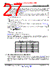
25 / 91 page  [ ] c ref f 9.8304 f MHz 512 ³ > [ ] c ref f 9.8304 f MHz 256 ³ > xosc ref f f REF _ DIV 1 = + c ref 3 FREQ 0.5 DITHER f f 2 16384 + ´ æ ö = ´ + ç ÷ è ø c ref 3 FREQ 0.5 DITHER f f 4 32768 + ´ æ ö = ´ + ç ÷ è ø Not Recommended for New Designs NRND CC1021 www.ti.com SWRS045D – JANUARY 2006 – REVISED JANUARY 2015 5.8 Frequency Programming Programming the frequency word in the configuration registers sets the operation frequency. There are two frequency words registers, termed FREQ_A and FREQ_B, which can be programmed to two different frequencies. One of the frequency words can be used for RX (local oscillator frequency) and the other for TX (transmitting carrier frequency) in order to be able to switch very fast between RX mode and TX mode. They can also be used for RX (or TX) at two different channels. The F_REG bit in the MAIN register selects frequency word A or B. The frequency word is located in FREQ_2A:FREQ_1A:FREQ_0A and FREQ_2B:FREQ_1B:FREQ_0B for the FREQ_A and FREQ_B word respectively. The LSB of the FREQ_0 registers are used to enable dithering (see Section 5.8.1). The PLL output frequency is given by Equation 2 in the frequency band 402 to 470 MHz, and by Equation 3 in the frequency band 804 to 960 MHz. (2) (3) The BANDSELECT bit in the ANALOG register controls the frequency band used. BANDSELECT = 0 gives 402 to 470 MHz, and BANDSELECT = 1 gives 804 to 960 MHz. The reference frequency is the crystal oscillator clock frequency divided by REF_DIV (3 bits in the CLOCK_A or CLOCK_B register), a number between 1 and 7, as shown in Equation 4. (4) FSK frequency deviation is programmed in the DEVIATION register. The deviation programming is divided into a mantissa (TXDEV_M[3:0]) and an exponent (TXDEV_X[2:0]). Generally REF_DIV should be as low as possible, but the requirements shown in Equation 5 must be met in the frequency band 402 to 470 MHz. (5) The requirements shown in Equation 6 must be met in the frequency band 804 to 960 MHz. (6) The PLL output frequency equations give the carrier frequency, fc , in transmit mode (centre frequency). The two FSK modulation frequencies are given by Equation 7 and Equation 8. f0 = fc – fdev (7) f1 = fc + fdev (8) Where: fdev is set by the DEVIATION register. fdev is set by the DEVIATION register shown in Equation 9 in the frequency band 402 to 470 MHz. fdev = fref × TXDEV_M × 2 (TXDEV_X –16) (9) fdev is set by the DEVIATION register shown in Equation 10 in the frequency band 804 to 960 MHz. fdev = fref × TXDEV_M × 2 (TXDEV_X –15) (10) OOK (On-Off Keying) is used if TXDEV_M[3:0] = 0000. The TX_SHAPING bit in the DEVIATION register controls Gaussian shaping of the modulation signal. Copyright © 2006–2015, Texas Instruments Incorporated Detailed Description 25 Submit Documentation Feedback Product Folder Links: CC1021 |
|
Enlace URL |
| ¿ALLDATASHEET es útil para Ud.? [ DONATE ] |
Todo acerca de Alldatasheet | Publicidad | Contáctenos | Política de Privacidad | Enlace a la hoja de datos | Intercambio de Enlaces | Lista de Fabricantes All Rights Reserved©Alldatasheet.com |
| Russian : Alldatasheetru.com | Korean : Alldatasheet.co.kr | Spanish : Alldatasheet.es | French : Alldatasheet.fr | Italian : Alldatasheetit.com Portuguese : Alldatasheetpt.com | Polish : Alldatasheet.pl | Vietnamese : Alldatasheet.vn Indian : Alldatasheet.in | Mexican : Alldatasheet.com.mx | British : Alldatasheet.co.uk | New Zealand : Alldatasheet.co.nz |
|
Family Site : ic2ic.com |
icmetro.com |
 Mexican ▼
 English
 Chinese
 German
 Japanese
 Russian
 Korean
 Spanish
 French
 Italian
 Portuguese
 Polish
 Vietnamese
 Indian
 Mexican
 British
 New Zealand